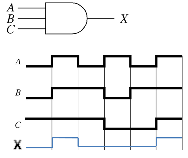
A timing diagram is a graph of the output of a logic gate with respect to the inputs of the gate. A timing diagram plots voltage (vertical) with respect to time (horizontal). A timing can also be seen as waveforms on an oscilloscope or on a logic analyzer. In order to determine the proper output waveform from a logic gate, simply divide the input diagrams into time segments where the inputs are constant and determine the state of the output (high or low) for that segment from the truth table. If the situation comes up where it does not make any difference which state an input is in (either way the output does not change), the input is said to be in a don't care condition.

Content ©2013. Some Rights Reserved.
Date last modified: January 17, 2013.
mobile page

![]()